 |
|
|
| |

BALANCING MACHINES - WHY BALANCE CRANKSHAFTS AND ENGINES? LET US EXPLAIN...
| Download Adobe PDF of this article here! |
![]()
Simply put, the main reason is to eliminate damaging and parasitic forces that causes unwelcome mechanical activity and robs the engine of its ability to freely transmit all of its power directly to the wheels.
Most people overlook the fact that all engines from the first stage of manufacturing go through some process of balancing. When the crankshaft and all related components are manufactured they have to be shaped and weighed to meet a target weight specification.
The crankshaft is then designed with counter weights that offset the thrusting and rotating forces generated via the combustion activity that causes the engine to rotate. Ok this is generally known and understood.
But what we need to understand is that the engines that were used just a few decades ago were running at a relatively low RPM band as compared to the engines that we are currently receiving from the OEM’s. Notice that I am talking about the “Grocery Getter” not Hi-Performance. Let me give you some information that hopefully will get your attention.
When the OEM’s such as GM, Ford and Chrysler produced a typical vehicle they would generally accept a balancing specification of 2.0 Ounce-Inch tolerance, so what does that mean. The 2.0 ounce-inch tolerance means that on a typical crankshaft that has a total diameter of 6.0 inches it will have 18.95 grams of unbalance weight residually embedded in the outside edge of the counter weights.
When the engine is running @ 1000 RPM (just above Idle), the embedded weight will cause the rotating crank assembly to generate a centrifugal unbalance force of 3.56 pounds. As we increase the RPM to 2000 the unbalance force increases to 14.25 pounds and at 4000 RPM it is now 56.5 pounds and 8000 RPM will generate 228 pounds of force.
Now you must understand even though the unbalance force has increased from 3.56 pounds to 228, the physical embedded weight of 18.95 is still exactly the same. Only by increasing the RPM can we increase the generated unbalanced force.
So you say we rarely operate the engine at 4000 RPM thus the 56+ pounds of force is not a big deal.
Well let me explain that if you had a 56 pound hammer and you dropped it on say the hood of your car you would notice an unwelcome dent. So lets imagine that hood of you car is an engine bearing. This bearing is receiving a pounding of this 56 pound hammer at a rate of 66+ times per second (4000 RPM).
Even though the bearing can probably handle the pounding force, the energy from this is transferred into the main bearing housing and it will cause distortion causing a host of new problems, especially with the newer light weight blocks. So if the bearing in your engine could talk then, …..well I think you are getting the picture.
Now while we can agree that the “Grocery Getter” won’t be seeing 8000 RPM regularly, you will notice that the RPM band has increased with the newer and smaller engines coming from the OEM’s. And based on the car that I just rented from Hertz, (and it had a Tachometer that listed 8000 RPM, which I did challenge, “sorry Hertz”), the engine demonstrated its ability to rev up but not without vibration. So it is fair to say there is more work to be done with reference to balancing.
So does balancing make horsepower?
No not in direct form, it eliminates parasitic forces that would otherwise increase with higher RPM.
Simply put if the combustion activity of the engine is the source of power then unbalance forces are the dampening or restricting forces that will waste the engines potential output. Elimination of vibrations and possible deformation as a result of the pounding activity is a welcomed benefit.
Professional engine builders understand that the unbalance forces change how engine parts interact with each other.
For instance, when Timing Chains were changed to Timing Belts one of the key benefits was that the belt help dampen the vibration pulses generated from the crankshaft and would eliminate or minimize their corruptive forces. Thus the camshaft would rotate more freely and would help stabilize the following activity of the lifter or cam follower.
It should be noted that as we have changed the engine designs and increased RPM and profiles of the camshaft, the vibration problems have generated a host of activities that are restricting the intended horsepower and durability increases.
Everyone in racing can agree that most of the major machining techniques and bolt-on parts have already been developed that will give quick and substantial horsepower increases. The pro engine builders are now searching for those last little tweaks of change, 1 horsepower at a time.
Balancing has a roll to play in this process, the ability of the engine component to maintain profile stability goes to its ability to perform as designed. Crankshafts are only one part of the equation.
Let me give you an example: The roller lifter is designed to follow the profile of the camshaft lobe with absolute accuracy. Consider a vehicle with perfectly balanced and round tires rolling along a smooth road surface. If you run off the side of the road the tire bounces due to the uneven terrain and as a result you feel the vibration in the steering wheel, the tire is still balanced but the surface that it is running on has changed forcing the tire to move in an unusual way loading and unloading the suspension spring that is carrying the load of the vehicle. Once back on the smooth highway the vehicle smoothes out and the ride is back to its normal profile.
The camshaft can and does go through a similar profile when the camshaft vibrates. But you are probably saying that the camshaft has been precision ground and does not have any attachments like a crankshaft and it is only turning a ½ the speed of the crankshaft.
We have analyzed hundreds of camshafts and have never found one that was close to being balanced.
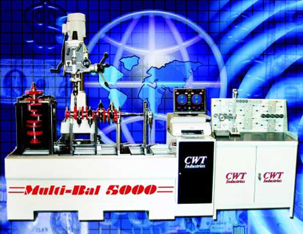
Shown below is a 60 mm Billet Camshaft that was analyzed on our Multi-Bal 5000 and the “Out of Balance” was reported at 1.2 Oz- Inch on the left side and 1.67 Oz- Inch on the right. Also note that the position indicator on the left side is pointing to 87 degrees and the right side is “0”, in a perfect world they should be pointing 180 degrees from each other.
First the “Out of Balance” forces are not opposed eliminating any potential to minimizing some of the unbalance force. Second there is enough physical weight on each side to cause a bending moment that will challenge the camshafts ability to maintain a stable shape and profile.
Now given the Camshaft running RPM of 4000 (1/2 of Crankshaft 8000 RPM) the left side of the camshaft is generating a force of 34.3 pounds and the right side is 47.6 pounds and both are hammering at 66+ times per second. This may be enough to cause the camshaft to become “excited” and set up a vibration pattern that will motivate the roller lifter to bounce on the surface of the lobe. Ultimately the valve will respond to all of this activity and most likely it will not be favorable.
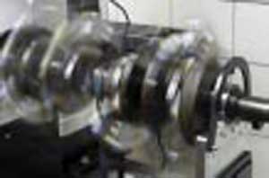
Back to the crankshaft.
As I stated before the crankshaft is designed to rotate smoothly and it has counter weights positioned to counteract the unbalance and thrusting forces caused during the running cycle.
You may have noticed that most true V-8 Hi-Performance Crankshafts are fully counter weighted (8 counter weights) this means the each rod journal has its own set of counter-weights. Most “Grocery-Getters” have 6 counter-weights. The 6 counter-weighted units are a carry-over from the older “stock” designs; remember they were not designed for high load and high RPM applications and did not generate large amounts of horsepower.
But all of us know that there have been hundreds of thousands that have been used in hi-performance applications. Through balancing these applications have performed admirably, but the fully counterweight units are better designed to handle disbursement of load and twisting forces that each pair of pistons & rods generate.
The counter-weight actually services two activities; one is to counter the offsetting weight from the piston and rod assemblies but also to help dampen the torsional activity caused from the firing sequence of the engine. But regardless of the number of counter-weights you must still dynamically balance both types.
Let’s Get Started!
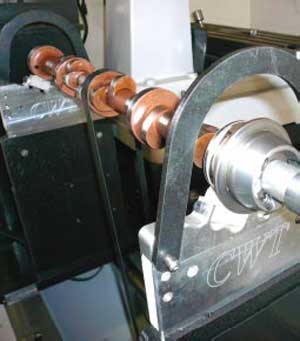
The first thing that we have to do is get the weight of all of the rotating and reciprocating parts. Using the supplied Weight Scale System from CWT we start by weighing the Connecting Rods.
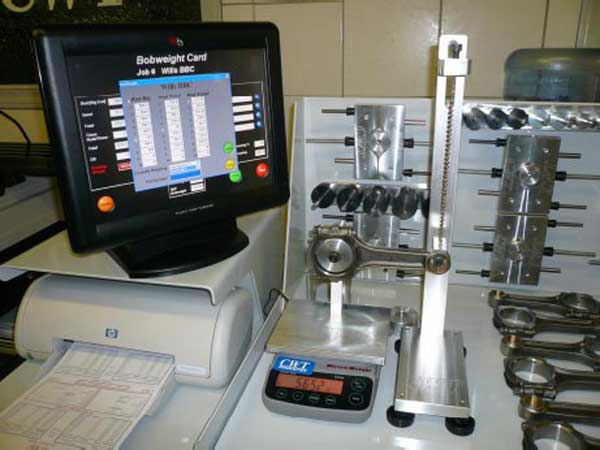
With this type of setup the weight values are directly sent to the computer software that allows the operator to log-in the weight of the part plus add the part number and description for later recall.
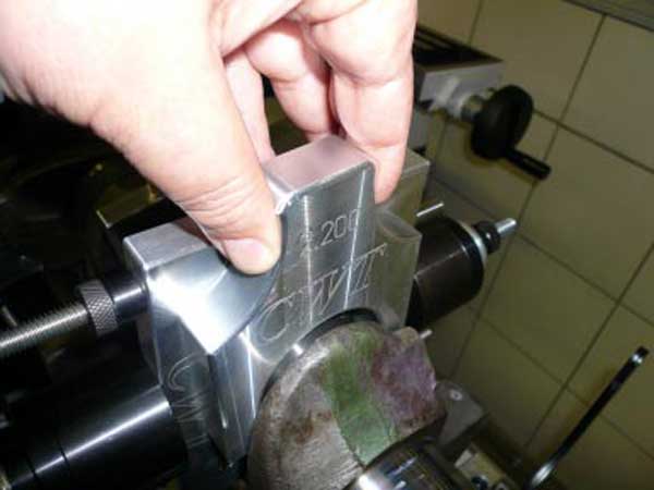
The rest of the parts (Pistons, Pins, Rings, Bearing etc.) are logged-in the same way giving the operator a targeted Bob-Weight. The technician will then attach precision weights to the “Moment-Matched” Bob-Weight bodies and mount them on the Crankshaft using the optional CWT alignment tool.
The Crank Assembly description is logged into the computer and the system is ready to be spun.
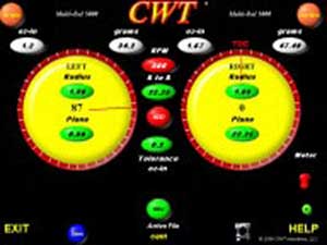
It takes about 20 seconds for the machine to determine both the position and magnitude of unbalance and display the data for the technician.
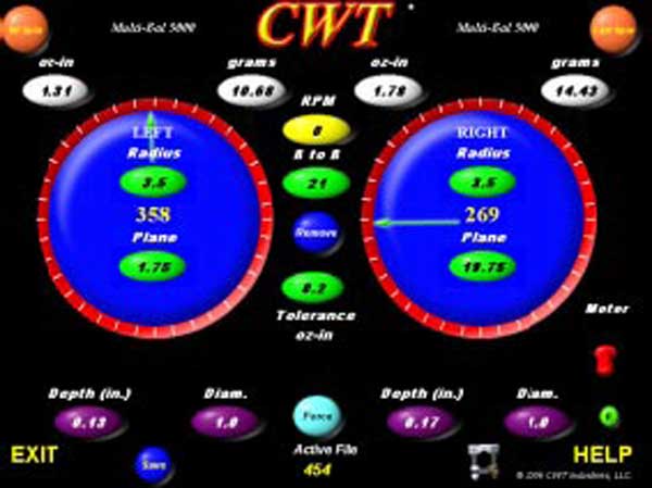
This particular example shows the left side unbalance @ 1.31 Oz-in and the right side @ 1.78 Oz-in. It also is telling the operator to remove 10.68 grams of weight from the outside edge of the crankshaft or if you decide to drill then by using a 1” drill you will need to drill .130 of an inch at the TDC Point.
The right will require .170 of an inch when the crankshaft is rotated to the assigned TDC Point on the right side of the screen.
After these corrections are made the machine reported the following results.
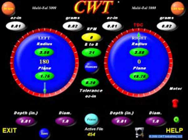
Notice that the magnitude of unbalance force has been reduced to 0.01 for both sides and that the position of any residual unbalance is equally opposed from the right and left side (180 degree). This crankshaft assembly is correctly balanced.
As you can see the process is very simple and through the help of advanced technology in the Multi-Bal 5000 HMVF the entire process can be done quickly and accurately. One key feature that is embedded into the 5000 series is a process defined as “Third Plane Analysis”. This advanced feature is superior to 2 plane or some times call plane separation machines that have been in the market.
In both previous visual examples (Camshaft and Crankshaft) you may notice that the unbalance forces we not opposed from each other. When this particular event takes place the 2 plane balancers have limited abilities to truly identify magnitude and position of the unbalance, they get close if the disparity in magnitude between each other are reasonably close. But when you have large amounts of weight differences and non-offsetting of the unbalance position, they become confused and misreport.
Technicians have had to learn to lower the weight on each side in small increments while noticing that the position and magnitude on the opposite side of the crankshaft were being simultaneously effected.
Eventually they would get the unit balanced to tolerance and in some cases the crankshaft would look like “Swiss Cheese”. All of this is a direct result of the technician having to chase the unbalance due to misreporting by the machine.
The 5000 series Software and Hardware are able to recognize the “Out of Couple” and “Differential of Magnitude” environment and through the proprietary software algorithms the collective forces of the left plane and right plane are properly analyzed showing how these forces can work in concert to generate a third plane. This activity is what disrupts the reporting ability of 2 plane or plane separation style balancing machines.
The 5000 series eliminates the mental gymnastics that the other machines force you into and simply cuts to the chase giving accurate reports of position and magnitude allowing the technician to accurately and proficiently process the job.
For more information on specific balancing activities such as “Heavy Metal Installation”, Crankshaft Counter Weight Shaping”, “Multi-Hole Drilling”, Bob-Weight Types and Positioning Procedures” and/ or “Bob-Weight Formulas” then stay tuned on this website - or call 800-449-1849
Welcome to CWT Industries  See the CWT Multi-Bal 5000HD (Heavy Duty) balancing machine spinning a 1200 LB Cummings QSK-60 16 cylinder crankshaft on the Multi-Bal 5000 crank balancer webpage and our the movie of the HD model balancing machine on the product movies page |
| CWT specializes in balancing machines, crank and crankshaft balancers, line hones, and more. We can build balancing machines for powerplants, pumps, generators, and power system applications. Give CWT a call today! |